HoveringAUV
Images
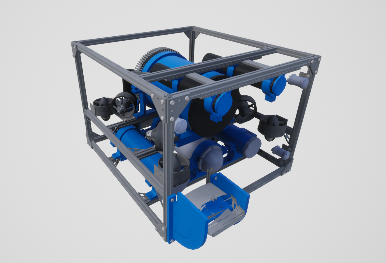
Description
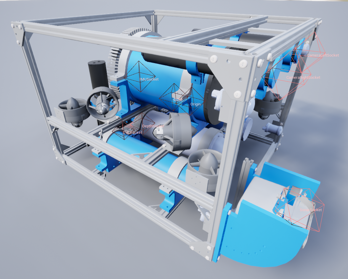
Our custom in-house hovering AUV.
See the HoveringAUV.
Control Schemes
- AUV Thrusters (``0``)
An 8-length floating point vector used to specify the control on each thruster. They begin with the front right vertical thrusters, then goes around counter-clockwise, then repeat the last four with the sideways thrusters.
- PD Controller (``1``)
A 6-length floating point vector of desired position in the global frame and roll, pitch, and yaw. A basic PD controller has been implementing to move the vehicle to that position and orientation using the needed forces and torques.
- Custom Dynamics (``2``)
A 6-length floating point vector of linear and angular accelerations in the global frame. This is to be used for implementing custom dynamics. Besides collisions, all other forces and torques - including gravity, buoyancy, and damping - have been disabled in the simulator to allow for a clean slate for custom dynamics.
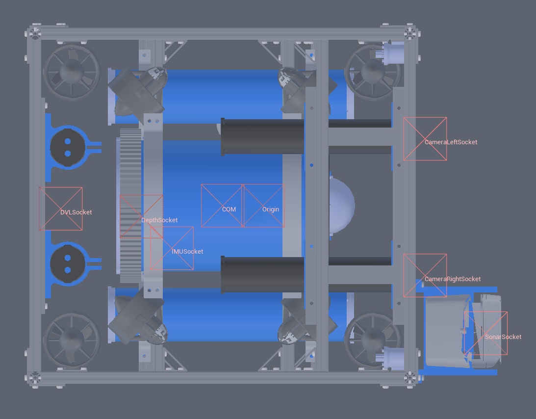
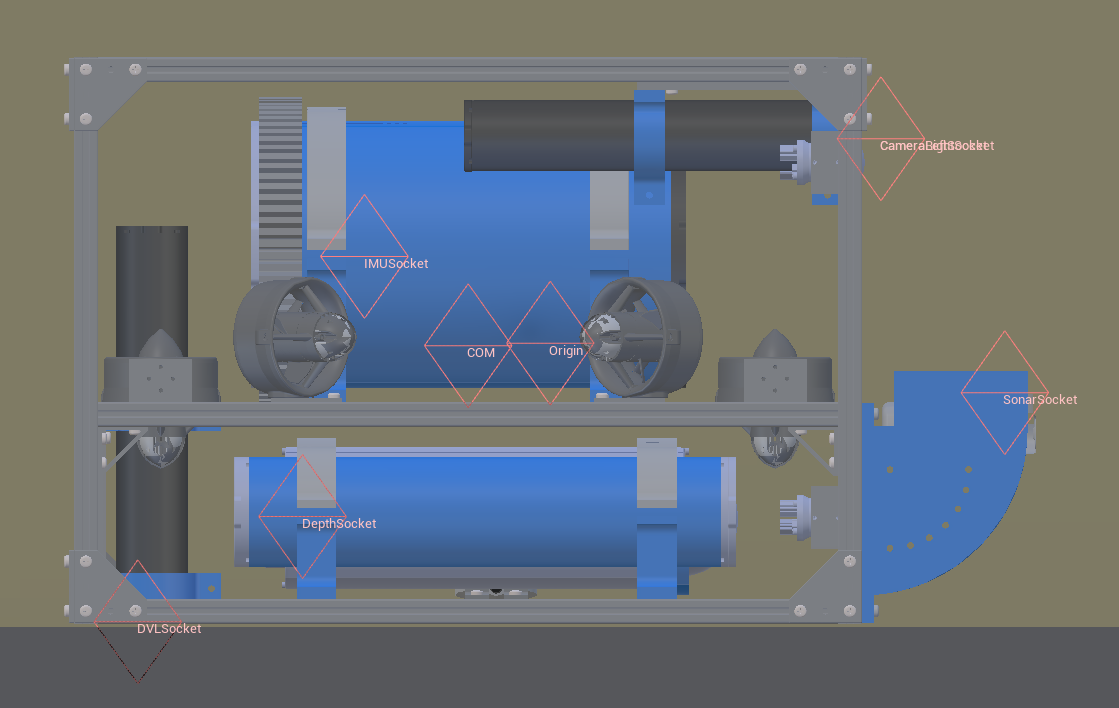
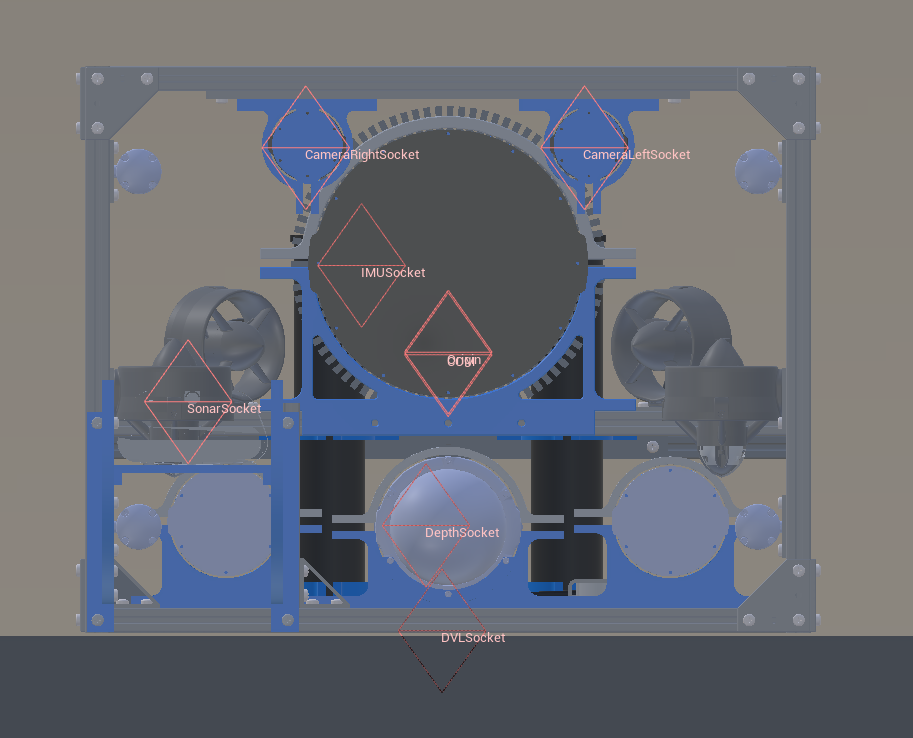
Sockets
COMCenter of massDVLSocketLocation of the DVLIMUSocketLocation of the IMU. Rotated 180 on x axis, i.e. in a NED frame instead of NWU.DepthSocketLocation of the depth sensor.SonarSocketLocation of the sonar sensor.CameraRightSocketLocation of the right camera (when looking in the same direction that the AUV is facing).CameraLeftSocketLocation of the left camera (when looking in the same direction that the AUV is facing).Origintrue center of the robotViewportwhere the robot is viewed from.